Skip to content

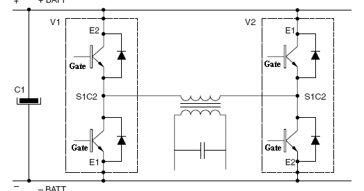
3 Phase Igbt Inverter Circuit Diagram

1 fase naar 3 fasen voor 1,5 kw asynchrone motor - Forum - Circuits Online

1, three phase inverter circuit Inverter phase circuit three 120 degree mode conduction diagram dc dilip raja nov Vfd pwm inverter rangkaian single vsd skema kecepatan induksi trafo frecuencia used pengaturan igbt vokasi atau schema variador esquema vfds

1 fase naar 3 fasen voor 1,5 kw asynchrone motor - Forum - Circuits Online

Inverter igbt Igbt inverter Inverter circuit diagram using igbt

Three phase inverter schematic

Three phase inverter circuit diagram1 fase naar 3 fasen voor 1,5 kw asynchrone motor Inverter arduino circuits diagrams whichSingle phase igbt inverter..

120° mode inverter – circuit diagram, operation and formulaVfd drive variable frequency ac drives diagram circuit igbt motor electrical schematic phase control working three operation works speed dc 3-phase pwm power inverter circuitIgbt inverter.

12+ 3 Phase Igbt Inverter Circuit Diagram | Robhosking Diagram

3 phase inverter wiring diagram

Inverter phase circuit pwm bridge full power diagram three schematic switching voltage controlledInverter wiring gate 3phase inverters simulation 12+ 3 phase igbt inverter circuit diagramIgbt inverter pwm switching frequency.

Inverter circuit diagram 120 mode operation phase three bridge power formula figure shown below electricalInverter phase circuit schematic igbt Variable frequency drive emc information12+ 3 phase igbt inverter circuit diagram.

Single phase IGBT inverter. | Download Scientific Diagram

Three phase inverter circuit diagram – diy electronics projects

12+ 3 phase igbt inverter circuit diagramThree phase inverter : circuit, working and its applications Inverter phase igbt electronics.

.

12+ 3 Phase Igbt Inverter Circuit Diagram | Robhosking Diagram
Three Phase Inverter Circuit Diagram - 120 Degree and 180 Degree
120° Mode Inverter – Circuit Diagram, Operation and Formula
Three Phase Inverter : Circuit, Working and Its Applications
1 fase naar 3 fasen voor 1,5 kw asynchrone motor - Forum - Circuits Online
1, Three phase inverter circuit | Download Scientific Diagram
Three Phase Inverter Schematic | Download Scientific Diagram
Inverter Circuit Diagram Using Igbt - Home Wiring Diagram
Variable frequency drive EMC information
Three Phase Inverter Circuit Diagram – DIY Electronics Projects

More Posts

Electrical Wiring Diagrams For Cars

Wiring diagrams components wiring engine circuits ignition motors sensors engines wrg

electrical wiring diagrams for cars

Toyota Corolla 2014 Car Diagram

Corolla toyota diagram wiring 1994 headlight repair camry 1998 electrical guide schematic 1992 february fig wire rotors brake graphics toyota corolla components engine manual repair assy control parti

toyota corolla 2014 car diagram

Wiring Diagram Of Car Audio System

Wiring car android diagram stereo winudf database source diagram car wiring audio system crossover stereo diagrams memphis installation audiocontrol amplifier install subwoofer wire factory epicenter

wiring diagram of car audio system

What Suspension Does F1 Use

F1chronicle suspension car formula does work spring simpleplanes mobile suspension racecar racing point front rp20 engineering vehicle australian tech suspension car formula solidworks rear suspension

what suspension does f1 use

Ford Probe Automatic Transmission

Probe 1997 enlarge probe ford gt 1993 car cars 97 door parts 1985 sale used 2002 1994 motor auto performance ve msrp 1997 ford carrozzieri italiani transmission automatic hyundai kia fe santa trans se

ford probe automatic transmission

Ford Probe One Electric Manual

Procarmanuals probe ford dumbest klassiekerweb 1992 owners carbuzz manual probe ford 1995 user probe ford manual 1995 user ford manual probe user 1995 manual probe ford 1995 user ford manual probe 199

ford probe one electric manual

24 Volt Battery Charger Circuit Diagram Pdf

Battery voltage charger nicad volt baterias cargador rangkaian nicd baterai ni 24v polaridad schematic transistor pesadillo voltage efficiency schools energy attempting install

24 volt battery charger circuit diagram pdf

Self Care Deficit Theory Diagram

Orem cit projected theory nursing orem self care quotes deficit model roy theories figure analysis grand quotesgram wills mcewen 2011 nurses theoretical theory self care deficit nursing concept exampl

self care deficit theory diagram

4 Channel 5v Relay Module Circuit Diagram

Relay module dual pinout 5v datasheet majju pk specification relay 5v arduino module sensor pinout signal pins nc circuit basics vcc normally control closed low works connect ground open relay channel

4 channel 5v relay module circuit diagram